AUTODESK HSM AND COMPOUND MITER MACHINING
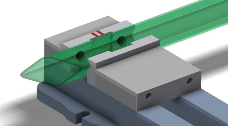
The topic of the post is two-fold: one, we need to introduce Lean Machine's integration of Autodesk's HSM programming for all of our mills and lathes; second, we want to show a really cool compound miter cut on the end of a steel tube. Below is a CAD model from Autodesk Inventor. The really neat thing about HSM is that it allows us to program directly inside of Inventor so there is no need to have a translation file in between CAM (Computer Aided Machining), or a separate CAM program.
The steel tube that we are going to cut has been changed to semi-transparent for illustration purposes.
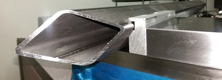
Doing a compound cut would normally require a 4 or 5 axis milling machine. Instead, we created angled and twisted jaws for our vises.
The steel tube that we are going to cut has been changed to semi-transparent for illustration purposes.
Doing a compound cut would normally require a 4 or 5 axis milling machine. Instead, we created angled and twisted jaws for our vises.
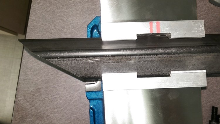
This is the top view of the set-up. Note the marking lines on the back jaw to make sure they go back in the machine correctly. The same marks are in the CAD model, so everything matches when the machinist sets up the job.
This is the top view of the clean precise cut that the mill provides.
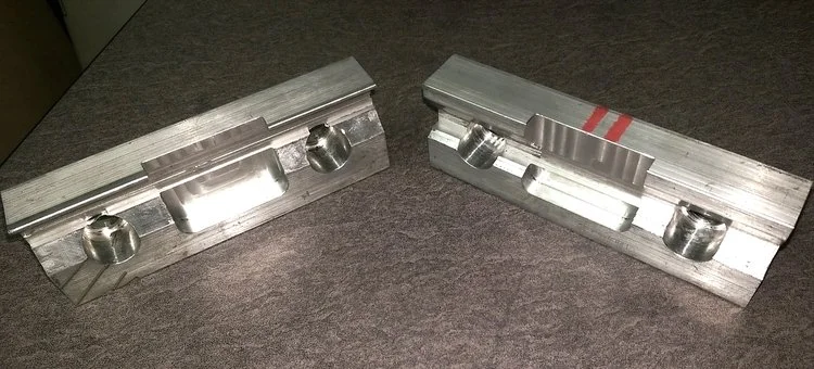
These are the front and back vise jaws removed from the vise; they were machined from solid aluminum.


